PROBA/CHRIS Processing#
Introduction#
The KARIOS tool can be easily integrated into a more complex geometric calibration processing.
This is what has been proposed as prototype in the context of PROBA-1/CHRIS Heritage Mission (ESA/ QA4EO 2 project) RD-10. With the objective of creating a multi-temporal dataset, achieving a good registration of input PROBA-1 images against a reference map is mandatory.
There were several concerns regarding geometric quality of PROBA-1 images. The a priori geolocation accuracy of input image is rarely below 5.0 km and cannot be improved due to missing telemetry. Input images are generally strongly distorted.
The general process is summarized in this chart :
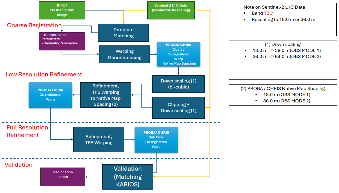
CHRIS Process Summary#
1. Coarse Registration#
A template matching algorithm can be used, followed by a re-alignment and scaling process. With an ORB matching process, translation, scale and rotation values are estimated and applied to the CHRIS template. The result template will then we compared to a S2 reference with KARIOS.
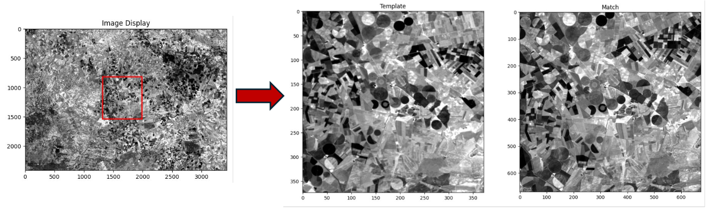
CHRIS Template Matching (left) and comparison with S2 (right)#
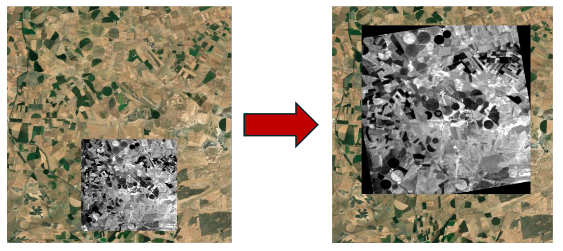
Alignment of the template over the reference#
2. High Resolution KARIOS matching#
Now that the image is aligned with the reference, KARIOS can be performed, initially at native resolution (18m) :
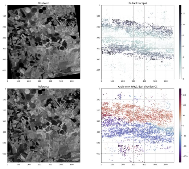
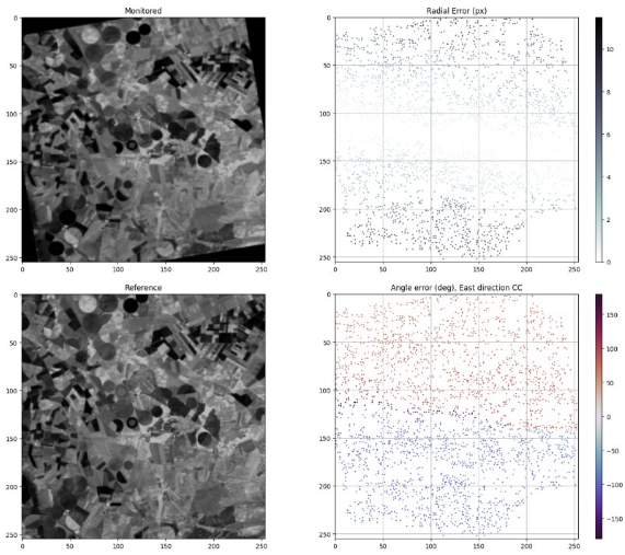
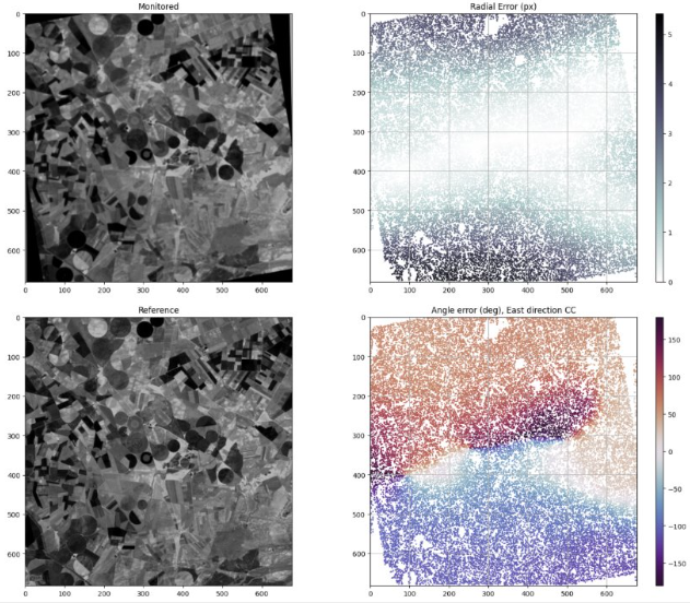
Geometric errors overview - CHRIS / S2 LiDAR before TPS correction (18m)#
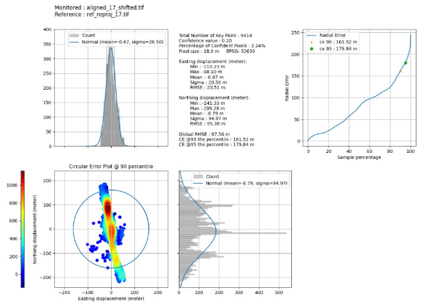
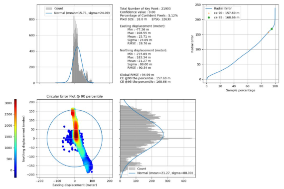
Geometric errors distribution - CHRIS / S2 LiDAR before TPS correction (18m)#
3. Low Resolution KARIOS matching#
The results show that the matching has only been performed partially. The corners near the center are captured whereas the ones in the upper and lower part of the image are not detected as the difference is too high. Thus, the final result is not meaningful for the whole image, and the TPS correction should not applied as the process depends on the detected corners. A downsampling can be performed to allow better matching (bi-cubic). A resolution of 48m is a good compromise between matching and not lowering too much information.
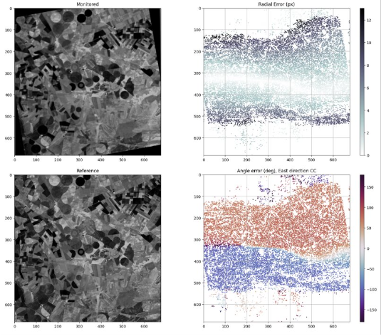
Geometric errors overview - CHRIS / S2 LiDAR before TPS correction (48m)#
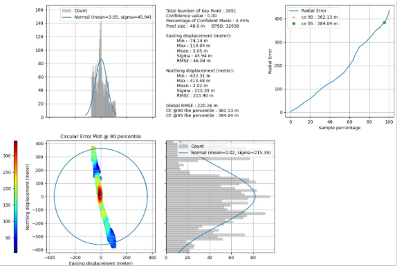
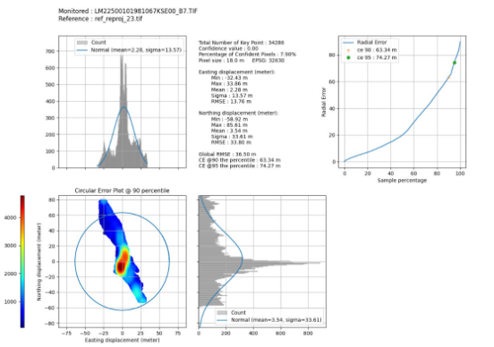
Geometric errors distribution - CHRIS / S2 LiDAR before TPS correction (48m)#
The corners now cover the entire image and show all the CHRIS deformations, though the point density is lower. The TPS correction can be applied by using a warping at full resolution.
3. Full Resolution Refinement#
The TPS algorithm yields the following results :
Geometric errors overview - CHRIS / S2 LiDAR after TPS correction (18m)#
Geometric errors distribution - CHRIS / S2 LiDAR after TPS correction (18m)#
The RMSE has been reduced, but the final matching could be improved. A second TPS correction process can be applied to the result image :
Geometric errors overview - CHRIS / S2 LiDAR after additional TPS correction (18m)#
Geometric errors distribution - CHRIS / S2 LiDAR after additional TPS correction (18m)#
The results now show a significant improvement in terms of metrics and the two images can now be compared with a full coverage at native resolution.
Note
You can cite KARIOS Tool by using Saunier, S., Canonicy, P., Louis, J., Debaecker, V., & Albinet, C. (2024). KARIOS : A fast & efficient open source tool for geometric deformation analysis (1.0). The Very High-resolution Radar & Optical Data Assessment (2023) Workshop (VH RODA), ESA-ESRIN, Frascati (Italy)
Many thanks to Telespazio for this open source tool.