SKYSAT / LiDAR Processing#
Introduction#
The KARIOS tool can be used for matching images from different sensor types, in the herein page the Geometric Registration of a Skysat image against a reference LIDAR image is reported.
This use case shows that KARIOS intermediate results should be carefully checked in order to define the most appropriate matching configuration (input parameters). Futhermore, beside configuration, image pre processing is also required.
1. Initial results#
The two images are first compared without any preprocessing, with a basic configuration :
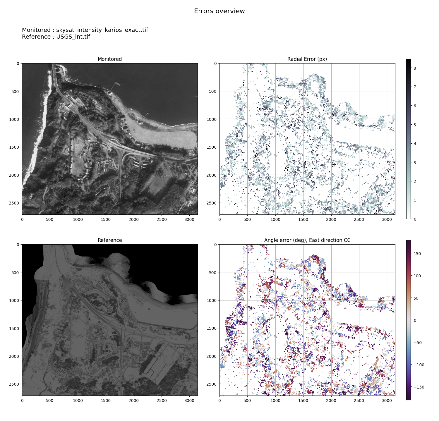
Geometric errors overview - Skysat / USGS LiDAR before opimization#
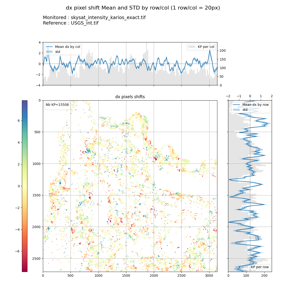
DX pixel shift (mean/STD) - Skysat / USGS LiDAR before opimization#
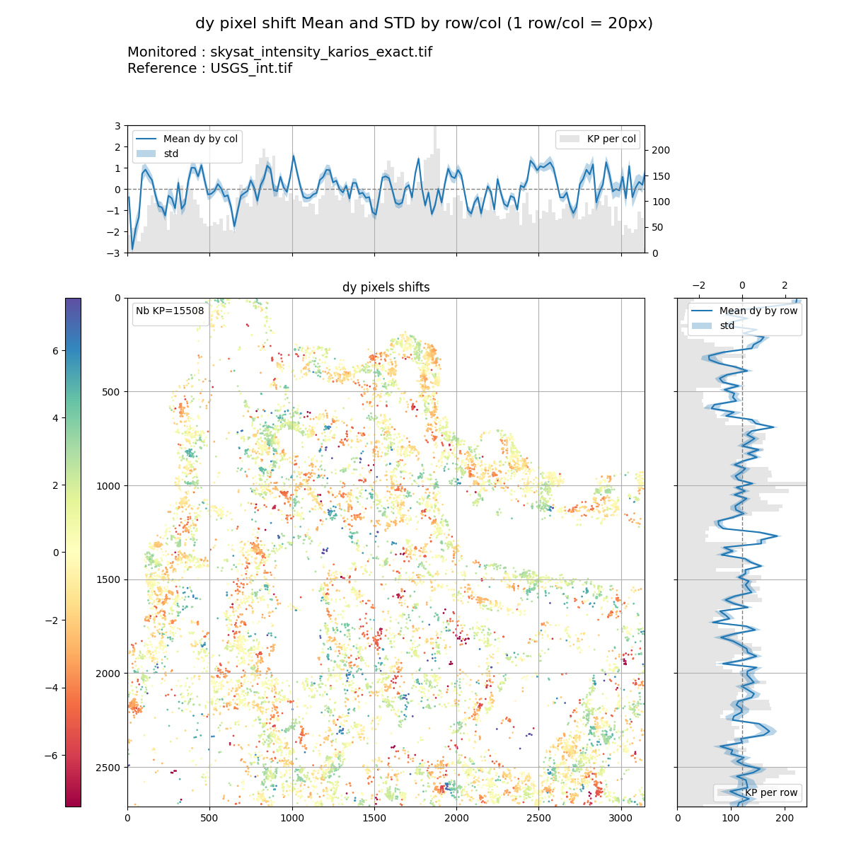
DY pixel shift (mean/STD) - Skysat / USGS LiDAR before opimization#
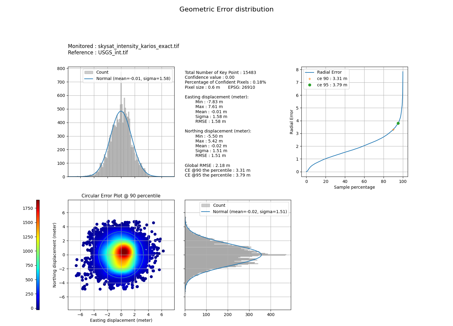
Geometric errors distribution - Skysat / USGS LiDAR before opimization#
Warning
Prefer performing the match on large areas
Always use images with int value
These results look good but are misleading as the algorithm does not provide a relevant matching. Manual measurements show a geometric shift which is close to 10m.
2. Laplacian optimization#
KARIOS tool matching approach is based on Kanade-Lucas-Tomasi feature detector algorithm. The two input intensity value images (Reference / Monitored) are filtered with Laplacian operator (high-pass filter, 2nd order derivation). Corners from Laplacian images are matched together using optical flow algorithms.
The same Laplacian filter is applied to both input images, even if the image spatial resolution is different.
A visual check of input Laplacian images is therefore recommended in order to evaluate If image corners can be matched :
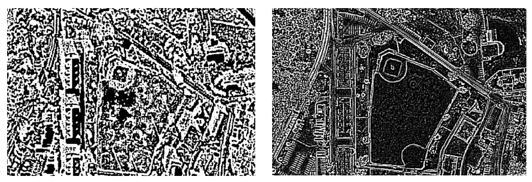
Computed laplacian - Skysat / USGS LiDAR before opimization#
In case the of Skysat (on the left) and LIDAR (on the right), significant differences are observed. In the LIDAR image, edges are very sharp compared to the ones in Skysat image, which are more blurred. Both images are also quite noisy.
A solution consists in applying a low-pass filtering (Gaussian filters, Median filters) to both images in order to get more comparable Laplacian image set. The laplacian kernel size can also be optimized in the KARIOS parameters.
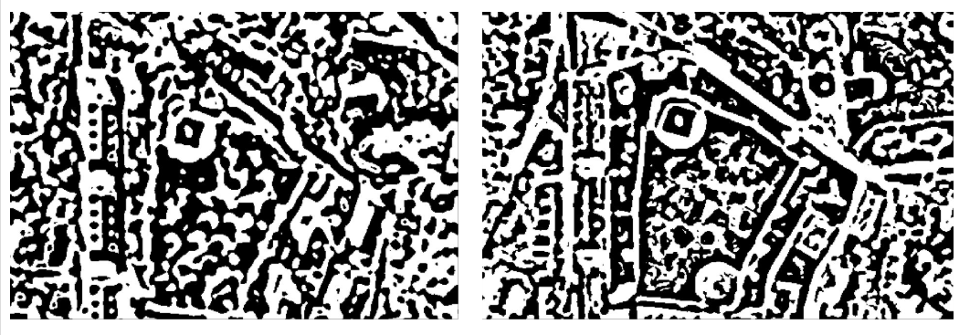
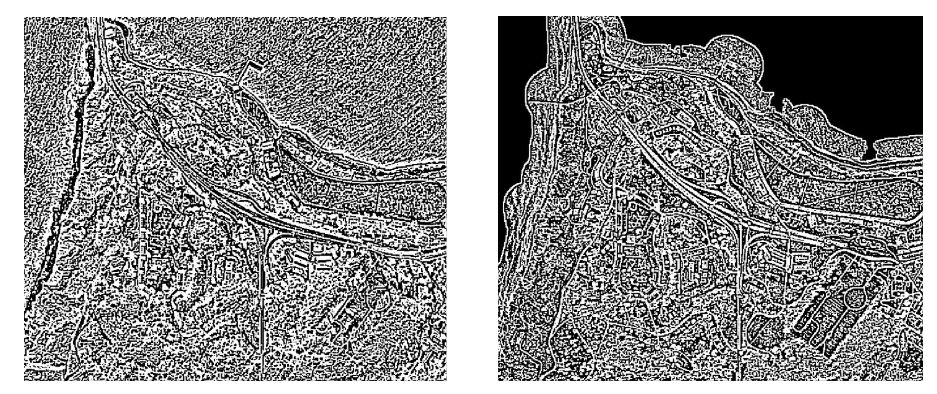
Computed laplacian - Skysat / USGS LiDAR after opimization#
As observed visually, the best configuration is to have:
Gaussian kernel size = 17
Laplacian kernal size = 13
Nevertheless, the KARIOS results show that the algorithm still does not captures the real geometric difference :
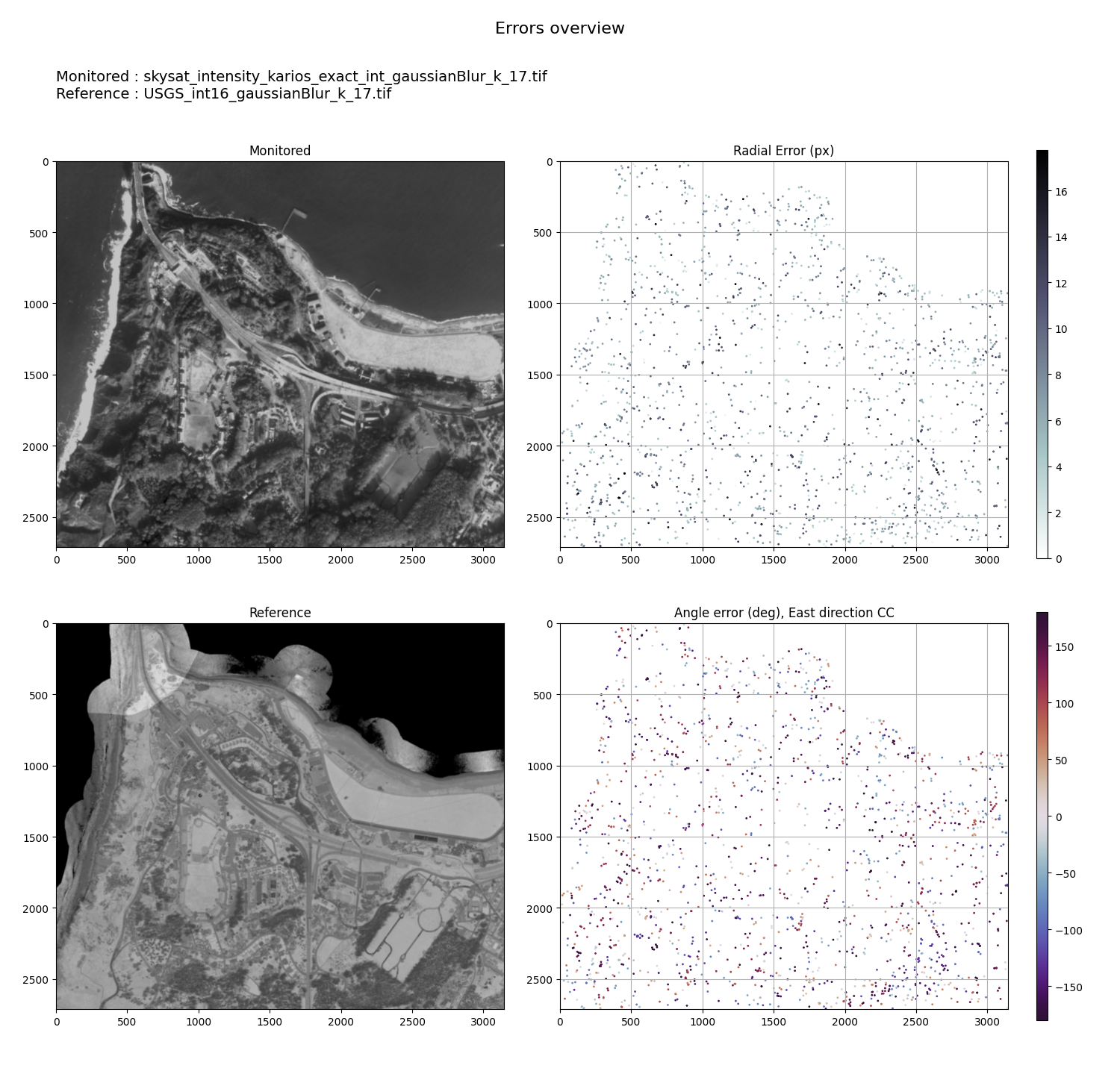
Geometric errors overview - Skysat / USGS LiDAR after laplacian opimization#
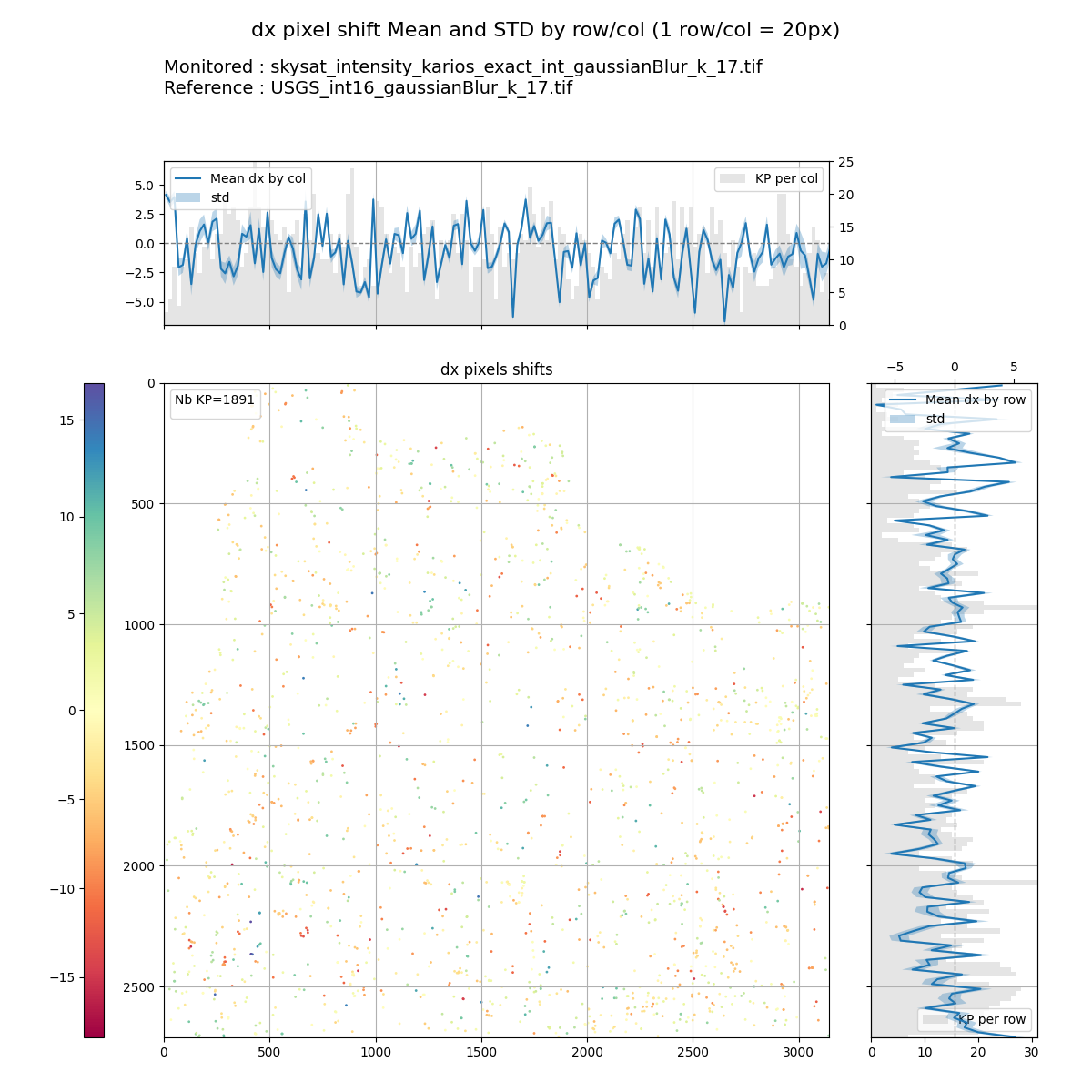
DX pixel shift (mean/STD) - Skysat / USGS LiDAR after laplacian opimization#
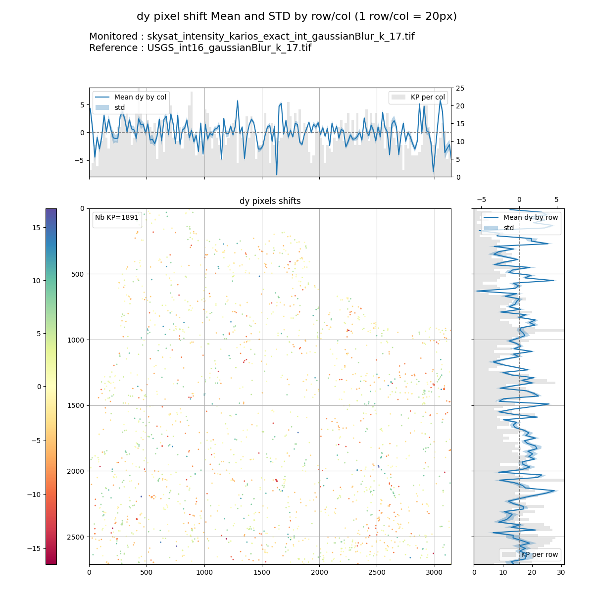
DY pixel shift (mean/STD) - Skysat / USGS LiDAR after laplacian opimization#
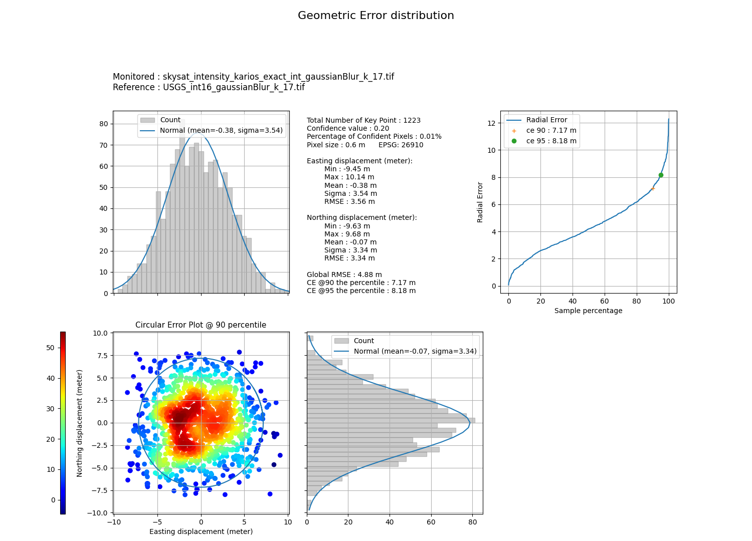
Geometric errors distribution - Skysat / USGS LiDAR after laplacian opimization#
3. Downsampling#
A second option consists in sampling the images to a lower spatial resolution, e.g 3.0 m pixel spacing (the original resolution was 0.5 m)
Indeed, KARIOS matching does not work at full resolution because of image quality issues, spatial resolution differences and geometric deformations.
Downsampling gives a smaller and more simple laplacian :
Computed laplacian - Skysat / USGS LiDAR at 3 meters#
Warning
This comparison shows the whole product, where previous laplacians were on a small part of the image.
This provides the following KARIOS results :
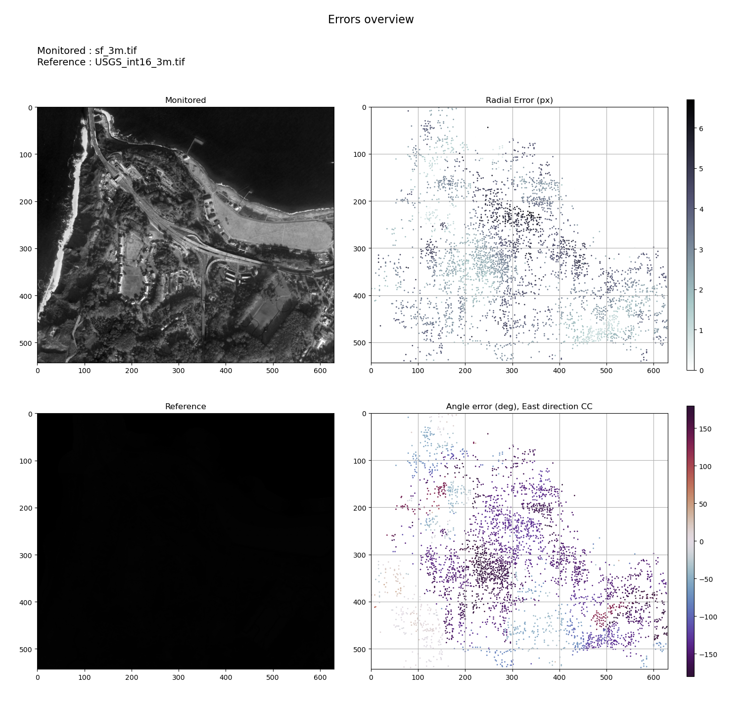
Geometric errors overview - Skysat / USGS LiDAR at 3 meters#
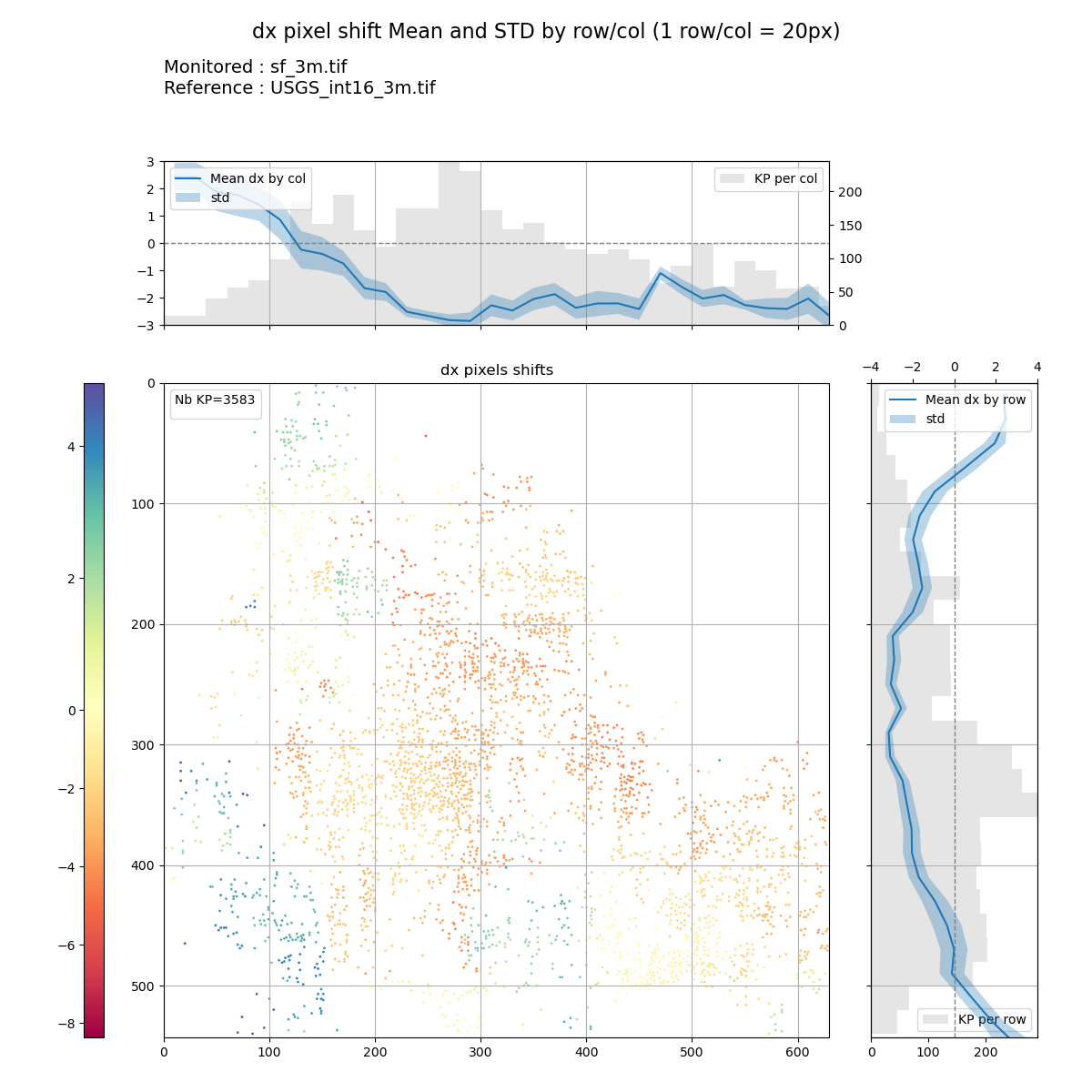
DX pixel shift (mean/STD) - Skysat / USGS LiDAR at 3 meters#
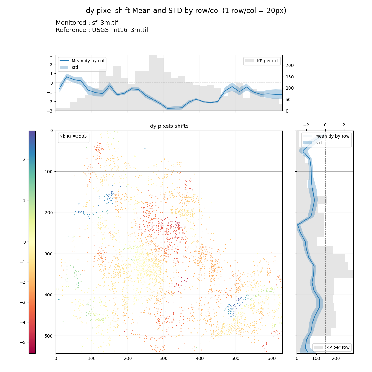
DY pixel shift (mean/STD) - Skysat / USGS LiDAR at 3 meters#

Geometric errors distribution - Skysat / USGS LiDAR at 3 meters#
The deformation can now be detected by the matching algorithm. In the end, downsampling is a good approach which provides accuracy within pixel, but precision is degraded. Results are consistent with the geometric deformations observed.
Conclusion#
KARIOS has been used to assess SKS image against LIDAR Image.
Pre-processing and downsampling are required to in order to fully assess SKS geometry.
Automatic image Matching and manual image measurements are matching.
Within the uncertainty budget, similar results (and shape) areachieved against S2 data.
When correcting SKS image for static error (about 5.0 m in both directions), uncertainty (RMSE) reaches 7.0 m.
Note
You can cite KARIOS Tool by using Saunier, S., Canonicy, P., Louis, J., Debaecker, V., & Albinet, C. (2024). KARIOS : A fast & efficient open source tool for geometric deformation analysis (1.0). The Very High-resolution Radar & Optical Data Assessment (2023) Workshop (VH RODA), ESA-ESRIN, Frascati (Italy)
Many thanks to Telespazio for this open source tool.